Wave soldering refers to the process where molten soft solder (lead-tin alloy) is pumped by an electric or electromagnetic pump to form a solder wave that meets design requirements, or alternatively formed by injecting nitrogen gas into the solder bath, allowing a printed circuit board pre-populated with components to pass through the solder wave, achieving mechanical and electrical connections between component terminals or leads and PCB pads through soft soldering.
Wave soldering involves bringing the soldering surface of a through-hole board directly into contact with high-temperature liquid tin to achieve soldering. The high-temperature liquid tin maintains an inclined surface, and a special device causes the liquid tin to form wave-like patterns, hence the name "wave soldering." Its primary material is solder bar.
Wave Soldering Methods
The adoption of wave soldering methods or processes depends on product complexity and production volume. For complex products with high output, nitrogen-based processes such as CoN▼2▼Tour wave can be considered to reduce dross and improve solder joint wettability. If using a medium-sized machine, the process can be divided into nitrogen-based and air-based processes. Users can still handle complex boards in an air environment; in such cases, corrosive fluxes can be used per customer requirements, followed by cleaning after soldering, or low-solids fluxes can be employed.
Introduction to Wave Soldering Temperature Curve
In the preheating zone, solvents in the flux sprayed on the circuit board evaporate, reducing gas generation during soldering. Meanwhile, rosin and activators begin to decompose and activate, removing oxides and other contaminants from the soldering surface and preventing re-oxidation of metal surfaces at high temperatures. The printed circuit board and components are adequately preheated, effectively avoiding thermal stress damage caused by rapid temperature rise during soldering. The preheating temperature and time for the circuit board should be determined based on the size, thickness of the PCB, dimensions and quantity of components, and the number of surface-mounted components. The preheating temperature measured on the PCB surface should be between 90~130°C; for multilayer boards or SMT kits with many components, the upper limit is used. Preheating time is controlled by conveyor belt speed. If the preheating temperature is too low or the time too short, solvents in the flux do not evaporate sufficiently, causing gas generation during soldering that leads to defects such as voids and solder balls; if the preheating temperature is too high or the time too long, the flux decomposes prematurely, losing its activity, which can also cause defects like icicles and bridging. To properly control preheating temperature and time and achieve optimal preheating, one can also judge by whether the flux coated on the bottom of the PCB before wave soldering remains tacky.
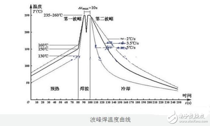
A qualified temperature curve must meet the following:
1: Preheating zone PCB bottom temperature range: 90-120°C.
2: Solder joint temperature during soldering: 245±10°C
3. Temperature between CHIP and WAVE must not be below 180°C
4. PCB immersion time in solder: 2--5 sec
5. Preheating temperature ramp rate on PCB bottom ≤5°C/s
6. PCB temperature at the exit of the oven should be controlled below 100°C
The temperature and duration in each zone are also determined by the temperature settings of each zone in the equipment, the molten solder temperature, and the conveyor belt speed. Wave soldering temperature curve measurement still needs to be determined through testing, and its basic process is similar to reflow profile measurement. Since the top side (component side, Top—orBoard) of the PCB is generally densely populated with SMT components, the temperature curve can be measured only on the bottom side. During testing, determine the conveyor belt speed, then record temperatures at at least three points on the test board bottom. Adjust heater temperatures repeatedly until each point meets the set curve requirements, then perform actual assembly testing and make necessary adjustments. When compiling process documents, in addition to recording the heating temperature curve settings, it is generally necessary to record the flux and its application process parameters (foam height, spray angle, pressure, density control requirements, and flux management), solder wave parameters, solder inspection, and dross removal requirements—these are all key process parameters for wave soldering.
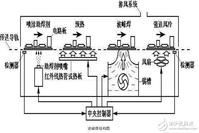
Wave Soldering Temperature Control Standards
?
1. Soldering temperature
Wave soldering temperature is an important process parameter affecting soldering quality. When the soldering temperature is too low, the spreading rate and wettability of the solder deteriorate, and since the pads or component terminals cannot be adequately wetted, defects such as cold solder joints, icicles, and bridging occur; when the soldering temperature is too high, oxidation of pads, component leads, and solder accelerates, easily causing cold solder joints. The soldering temperature should be controlled at 250+5°C.
?
2. Preheating temperature
The purpose of preheating is to allow solvents in the flux to evaporate fully, preventing interference with PCB wetting and solder joint formation when the board passes through the solder; and to bring the PCB to a certain temperature before soldering to avoid warping or deformation due to thermal shock. Generally, the preheating temperature is controlled at 180~200°C, with a preheating time of 1 to 3 minutes.
?
3. Conveyor inclination angle
The conveyor inclination angle has a significant impact on soldering results, especially when soldering high-density SMT components. When the angle is too small, bridging is more likely to occur, particularly in shadowed areas of SMT components during soldering; when the angle is too large, although it helps eliminate bridging, the solder amount on joints is too small, easily causing cold solder joints. Therefore, the conveyor inclination angle should be controlled between 5° and 7°.
?
4. Wave height
The wave height may vary slightly over the course of soldering operations and should be appropriately adjusted during the process to maintain the ideal height for soldering, with the solder immersion depth being 1/2 to 1/3 of the PCB thickness.